On a KISS basis - I tend to just use a bimetallic switch or omit the temperature control and just run the fan from power up. It's possible for a processor to suffer some non-handled exception where it no longer executes the temperature management routine.
I suggest that you give details of the iron (and tip) and solder that you are using and a close up photo of the wires that are being problematic.
The iron temperature control may be faulty and the iron just not getting to soldering temperatures. Or you may have it set too low.
The thermal mass of typical USB wires is so low that, if the solder actually melts freely at the tip end when not soldering anything, it should do so when soldering these wires.
Get them working on their mathematic skills, instead. You can give them a really good head start - mine could solve simple differential equations at age 11.
I'd suggest peeling off just one strand of the wire and use that. You will need to insulate the wire from the nail - Wrapping paper around the nail will do. You will need to insulate the wire from itself, so that adjacent turns don't touch. You can just space the turns out along the paper sleeve. That should do the trick. If you have twine, you can wind that on with the copper wire and use the twine to keep the turns from touching each other.
Oh to straighten copper wire, if you don't know this trick - hold your nail in a vice and wrap a single turn of copper wire around it. If you then pull on one end of the wire, keeping a little tension on the other - with a bit of practice it will give you a very straight end result, as the wire pulls away from the nail.
The standard way of looking at this is to consider a capacitor-resistor series combination going to ground. Connect a 10v (wrt ground) supply to the capacitor and the voltage across the resistor rises to +10v, then decays. Now connect that capacitor to ground and that same resistor gets -10v across it, which then decays. Whatever is connected to the capacitor "top" terminal has to be able to sink current as well as source it.
That's what generators in simulators do - they have zero internal impedance (usually). They sink currents as well as source them.
Lots of people use them for something similar. Obviously, the situation changes once the lines are power lines and not signal lines. If you can stabilise the result and add strain relief.
I think that it is the same stuff, just will propellant added in the aerosol. A small squeezy bottle with a needle is better if you have live stuff nearby - but you can always fill one from an aerosol
Assuming that the ribbon cable is standard - you could consider adding TWO IDC connectors, side by side. Then slice the cable through between them. Then add a standard extension cable to link the two. Indeed if one of the two is male, the other female - the extension can be removed if the thing is relocated to where the extension isn't needed - or a longer one is needed.
I confess to having done this sort of mod several times, myself. It's also quite an easy way of sticking a protocol analyser/sniffer between the two and/or modifying the data that is sent on its way. Or adding an additional sensor (even of a different type) and converting its output to something suitable.
You could use something like this:
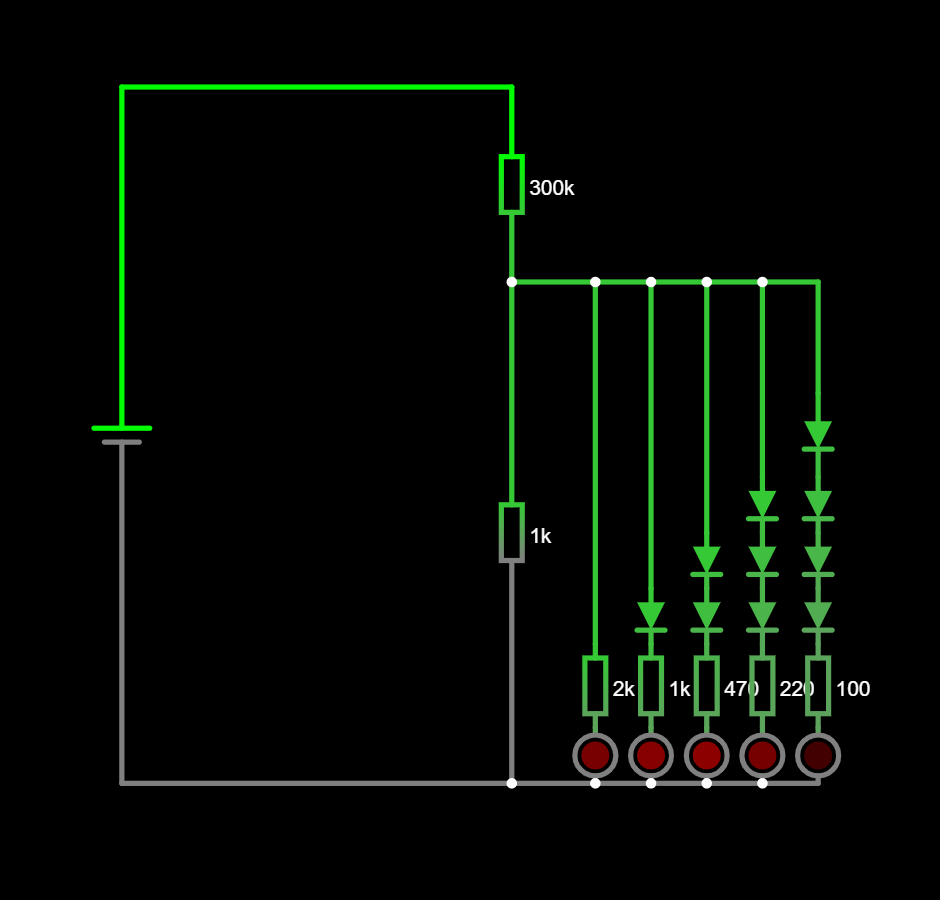
The diodes at least provide some steps - which just LEDs and resistors don't. The dissipation in the main series resistors will be quite something, also. (You will probably need several resistors in series, if you use standard ones, with their standard voltage limits).
How I would do it is to use two digital IO pins on the processor to generate the reference square wave. Put the sensor plus a series precision resistor between them and just pull one IO pin high as the other is pulled low and then swap them. That presumes that IO pins can both source and sink IO current. Then take the junction between the two to an Analogue in pin. You get two measurements each cycle. Use a lookup table of values and interpolate between them. If you wanted more precision - add more series resistors of different values covering the range of humidity that you want to sense, going to different IO pins. So you can choose the IO pin pair that brings the centre point between sensor and resistor closest to the mid-voltage point. It's effectively a balanced half bridge arrangement - using the precision of the resistors to determine overall measurement precision. OK it ties up several IO pins - but microcontrollers are so cheap, I'd probably just dedicate one to this sensor and that's all that it would do.
I'm assuming that those "v"s are meters and not constant voltage sources. A 2.4v zener does NOT have exactly 2.4v across it. A 1.2 v supply will not be precisely 1.2v. Both will also vary with time and temperature. So, in practice there WILL be a dc component across the sensor - which will destroy it.
I'm old school. I'd reverse engineer that part of the board, work out what the resistor was doing and then choose a value, much as the original designer did.
From that small section of the board - I'd guess that it is a resistor in the CR voltage dropper, used to power the electronics.
Depends on your programming abilities. You can set up a "1-Wire" bus and put the lot on that. You could have one microcontroller as master and the rest as slaves - your external USB connection would go to the master and it could, in theory at least, then pass on program upgrades to the others. Clearly they would all have to be programmed individually, originally. But, quite frankly, the investment in time and effort on setting all that up? If you had dozens, hundreds - then yes. But you only have a small hand full. I'd just bring out their USB connections and program them individually, via those. I think each one has a unique identifier, stored in ROM - so they could all run the same software and include that identifier in messages on the bus.
Sounds good to me (pun intended)...
Brilliant! Thanks you so much for taking the time and effort to help me with this - and for mentioning "CONNECTORBOOK.COM" so I can add that as a useful reference. Not a chassis mount but that always was a mission impossible to find, I suspect.
That sounds reasonable. That capacitor to ground may be needed for stability - lack of it could explain the problems that you have been experiencing.
Unless you are providing a bias voltage on the external input, a non-polarised capacitor is a better bet.
That sounds reasonable. That capacitor to ground may be needed for stability - lack of it could explain the problems that you have been experiencing.
Unless you are providing a bias voltage on the external input, a non-polarised capacitor is a better bet.
It's usually a good idea to look at what's normally connected, when breaking a circuit, and replicate that. Which I seem to remember is a 10k resistor with a parallel capacitor (being too lazy to go back and look again). You could try the same combination, in place of the added input cable, on the lines that you plan to use and see if it whines. If not, add the cable(s) and try again. That may stop it happening on all channels.
There are two muting methods - open circuit the input (via a switch or a gate) - in which case there will probably still be some signal transfer through capacitive coupling - especially if the amp side of the open circuit is high gain. Or short the signal path to ground - and that short will have some impedance and thus the signal is only attenuated and not removed all together.
Turning the amp gain to far higher than it ever would be in practice is hardly a fair test. There aren't many amps that will be noise free under those conditions - and, in this case, there will be a signal to amplify, albeit highly attenuated.
It's good to be cautious - cascade failure can be waiting to bite. Never direct connect unless unavoidable - add a series capacitor, if you can. Yes, not usually a good idea to provide a dc path unless essential and, even then, current limit it if possible.
I'm puzzled - you describe wanting to add a headphone jack (eg an output jack socket into which headphones can be plugged) - yet you seem to actually want a socket that provides auxiliary input.
However, if you are indeed trying to add external input and are disconnecting the inputs to an amplifier - you might want to tie those disconnected inputs to ground.
Can't find a 7.4 x 5.08mm female chassis mount socket - am I using the wrong description?
I have a 12v 6.67A power supply with a male co-axial plug (with centre pin) that's 7.4mm OD and 5.08mm ID. The metal tube is 12.5mm long.
The pin is recessed and about 1mm in diameter - which seems impossibly small for 6.67A.
A chassis mount socket that would take it would come in handy. But I don't seem to be able to find one. Am I just using the wrong search terms?
Any pointers much appreciated.
Using multiple windings on two transformers to create one output at maximum power
Hi everyone, I've just resurrected a broken Weller TCP1 and need a 24v ac supply for it.
I have a 23.5-0-23.5v toroid that I was just going to use half the winding - but it's overkill (8A rating) and going to be very big and heavy.
I've also got a pair of identical transformers with 8-0-8 and a 16-0-16 secondary windings.
I'm thinking of paralleling a 16v winding on each transformer, doing the same with an 8v winding and putting the two in series to give the 24v. However, that leaves two 16v windings and two 8v windings left unused.
Is there any advantage in paralleling those windings also? Any disadvantage? Or just leave them unconnected...Which is what I was about to do..
Sadly I cannot split either winding into two independent ones.
Using an incandescent lamp as the "resistor" for a zener/avalanche diode regulated supply
The recent post on using a lamp in series to limit potential fault currents has had me thinking about using them as above. Has anyone done this? I can see advantages, cost for one - wirewound resistors can be expensive. Visual indication of a varying load. Make it "short-circuit proof"..